Quick Downloads
Click to download complete PDF
2017 Brochure KUBOTA B3150 NEILO Broom
2017 Brochure KUBOTA B3150 NEILO Broom
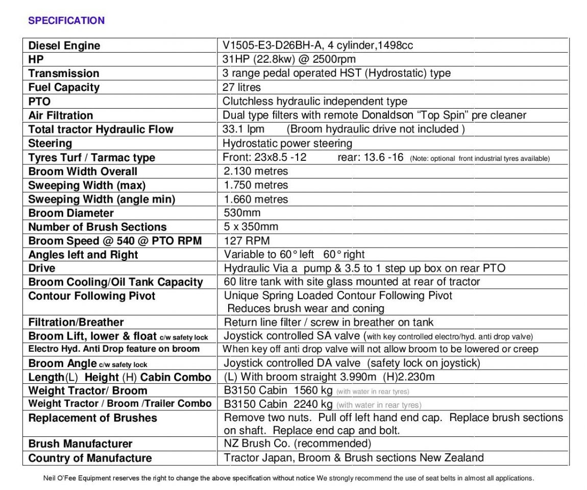
Other Machine Specifcations
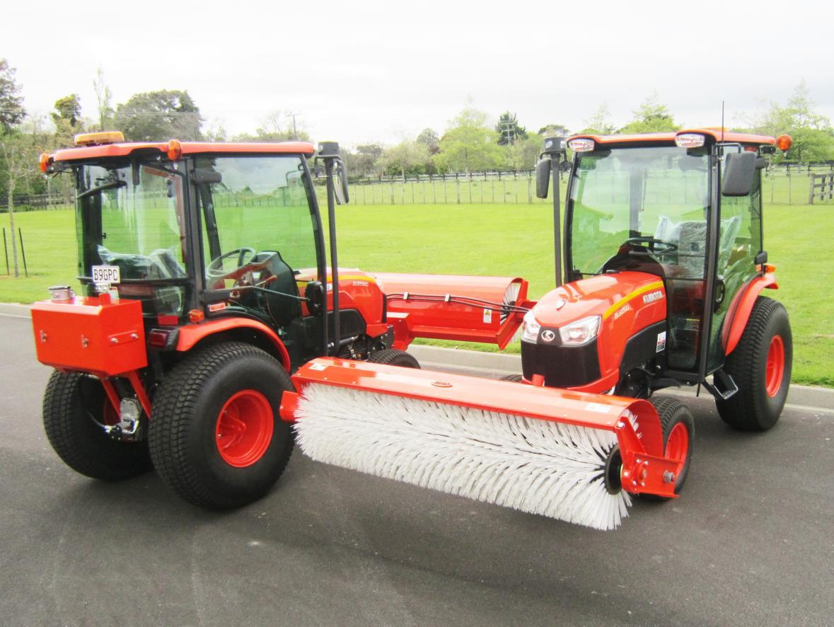
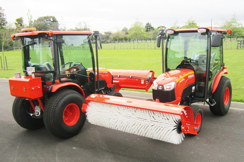
The legendary B Series Kubota & NEILO broom combo is compact enough to transport on a trailer yet rugged & powerful enough for the most demanding sealing contracts.
Over 150 Neilo Broom Combos in service in New Zealand Australia & South Pacific
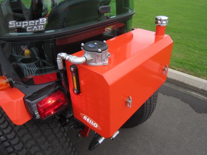
Protect your operators from the dust and the harsh weather with the 31HP Kubota B3150HST Tractor & NEILO broom combo with air Conditioned factory cabin.
The B3150 Broom Combo features a powerful Kubota 4 cylinder diesel engine, 3 range HST Hydrostatic transmission, and clutch-less hydraulic independent PTO to engage the broom pump.
We have combined the proven performance and reliability of the Kubota B Series with our unique broom technology to create the ultimate in compact easily transportable sweepers.
The B3150 Cabin Combo can be safely transported on a tandem trailer behind an average utility vehicle with a 2500kg tow rating.
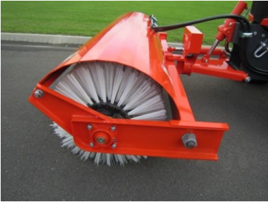
Our brooms spring loaded contour following lateral pivot substantially reduces brush wear and coning.
The Kubota Tractor & NEILO Broom Combo is ready for work as soon as you receive it complete with Class one LED Beacon and remote mounted “Top Spin” pre cleaner. A custom trailer is also offered.
- 31hp engine with 3 range HST Hydrostatic transmission
- Air conditioned & heated factory cabin
- Remote mounted “Top Spin” pre cleaner
- Front mounted 1.75 m 5 section hydraulic driven broom
- Pivoting type hyd. lift, float & hydraulic left right angle
- Convenient joy stick to control broom lift, float and angle
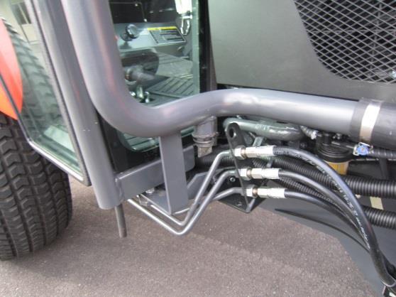
- Broom drive via PTO driven hydraulic pump
- Clutchless engagement of broom drive
- Filtered rear mounted 60 litre hyd. res. for max. cooling
- Operator can easily replace brush sections in the field
- Unique spring activated contour following lateral pivot ensures even brush pressure & reduced coning
Safety First
Before operation please read and understand the yellow safety section of the Kubota B3150 operator manual
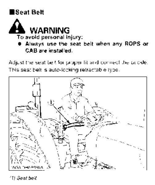
- Always wear a seat belt
- Always sit in the operators seat when starting the engine or operating levers and controls
- Never carry passengers
- Before dismounting the tractor stop engine, disengage PTO/ broom and engage parking brake
- There are dangerous pinch points and rotating parts in the vicinity of the front broom, do not operate with other personal in the vicinity
- Stop the tractor, disengage PTO broom drive, engage parking brake before attempting any adjustment or work on the tractor or broom
- Only operate the tractor broom with doors and windows fully closed
BASIC OPERATING PROCEDURE OF KUBOTA B3150HST TRACTOR WITH NEILO BROOM
For detailed operating and servicing procedures please see Kubota B3150 HST operator manual supplied
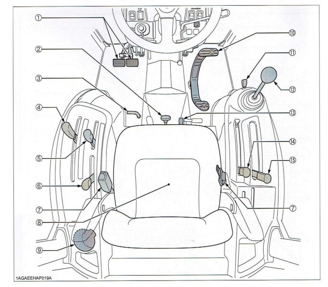
- Brake pedal
- 3 PL speed knob (disengaged)
- Differential lock Pedal
- Range gear shift lever
- PTO clutch (Broom Drive)
- PTO select Lever (disengaged)
- Seat belt
- Operators seat
- Cup Holder
- HST speed control pedal
- Broom lock lever
- Broom control joystick
- 4WD lever(disengaged)
- 3 PL position lever(disengaged)
- Cruise control lever
- Travel adjust lever
- Suspension adjust lever
- Arm rest
- Arm rest angle and adjust knob
- Backrest adjust lever
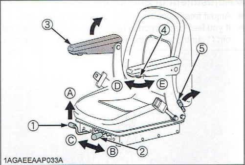
- A: “UNLOCK”
- B: “TO INCREASE TENSION”
- C: “TO DECREASE TENSION”
- D; “TO INCREASE ANGLE”
- E: “TO DECREASE ANGLE”
Travel adjustment
Unlock the travel adjust lever and slide the seat backward or forward, as required. The seat will lock in position when the lever is released.
Suspension Adjustment
Pull and slide the suspension adjust lever to desired tension or increase tension position while sitting in the seat.
Tilt Adjustment
Pull the backrest til adjust lever and tilt the backrest to the desired position.
Armrest
Armrest may be set at upright position if desired.
Armrest angle adjustment
Turn the arm rest angle adjust knob to the desired angle.
IMPORTANT:
After adjusting the operator’s seat, be sure to check to see that the seat is properly locked.
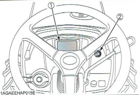
Tilt Steering Adjustment
To avoid personal injury:
Do not adjust the steering wheel while the tractor is in motion.
Press down the steering wheel pedal, to release the lock so the steering wheel can be adjusted to one of 3 desired positions.


(1) Steering wheel tilt pedal
(A) “PRESS DOWN”
Gauges:
Fuel Gauge
When the key switch is on, the fuel gauge indicates the fuel level.
Be careful not to empty the fuel tank. Otherwise air may enter the fuel system.
Should this happen, the system should be bled. (See “Bleeding Fuel System” in SERVICES AS REQUIRED” in “PERIODIC SERVICE” section)

(1) Fuel Gauge
(A) “EMPTY”
(B) “FULL”
Coolant Temperature Gauge
To avoid personal injury or death:
Do not remove radiator cap until coolant temperature is well below its boiling point. Then loosen the cap slightly to relieve any pressure before removing the cap completely.
- With the key switch “ON” , this gauge indicates the temperature of the coolant. “C” for “cold” and “H” for “hot”.
- If the indicator reaches the “H” position (red zone). engine coolant is overheated. Check the tractor by referring to “TROUBLESHOOTING” section.

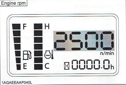
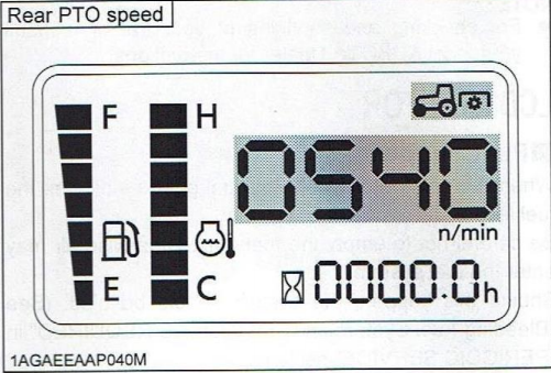
Engine RPM
PTO Speed
Changing Display Mode
- The LCD monitor give several different displays.
- The LCD monitor displays “Engine rpm” normally.
- The display switch is pressed, the display is switched to “Rear PTO speed” , “Mid PTO speed” , “Engine rpm”.
- LCD monitor
- Display switch
TO START TRACTOR
- Disengage the PTO (Broom drive)
- Ensure cruise control lever (# 1 page 5) is in rear position
- Ensure HST pedal (# 1 page 2) is in neutral position
- Set throttle at aprox. ½ speed
- For first start In cold weather hold the key on the pre-heat position for 0 to 5 seconds
- Start
- To stop tractor Turn key
- When key is off position, broom will be locked and cannot be dropped
Engine operating RPM
When driving the tractor always operate at 80 to 100% of available RPM (throttle) to ensure efficient operation of HST Transmission
ALWAYS WEAR A SEAT BELT!
HST is a fluid or hydraulic drive transmission.
HST allows infinite speed adjustment and instant forward to reverse travel via the foot pedal.
Components of the HST Transmission are:
![]()
- Cruise control lever
- HST speed control pedal
- Range change lever L-M-H
Range change lever 3
Select a suitable gear range depending on the type of work load. Ensure tractor is stationary before selecting gear.
L (low) M ( medium) H ( high)
L is the lowest and most powerful gear and will operate between
0 – 5.9 km/H.
Use for very heavy operations.
M is the medium-range and will operate between
0 – 8.7 km/H.
We recommend Medium as the most suitable gear for brooming operations.
H is the highest and least powerful gear and will operate between
0 – 18.5 km/H.
Use for light work and highway operations.
HST speed control pedal
- To move forward, slowly depress the front of the HST pedal
- The further you depress the HST pedal the higher the gear and the faster the tractor travels.
- To decrease speed or when the pulling requirement increases simply decrease pedal pressure.
Forward to reverse:
- To shuttle between forward to reverse simply step on front or rear of HST pedal
Cruise control lever
Caution: We do not recommend cruise control for highway use. When operating the cruise control we recommend leaving the right hand on the cruise control lever at all times
- Cruise control will manually override the HST pedal.
- Push the cruise control lever forward for a higher gear and the faster the tractor travels
Safety feature of cruise control:
- By stepping hard on the brake pedal or hard on the rear of the HST pedal and the cruise control lever will return to the neutral position.
Note: increased transmission noise may be experienced when cruise control engaged, this is normal
Engine braking and the HST transmission:
- Tractors with HST transmissions enjoy very effective engine braking.
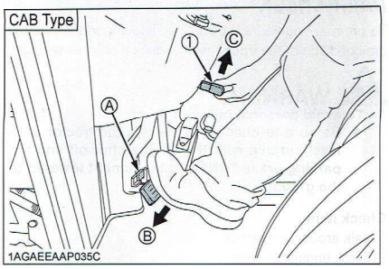
To set the parking brakes:
- Depress the brake pedal (a)
- Latch the brake pedal with the parking brake latch lever (1)
- To release parking brake step firmly on brake pedal.
4WD Four Wheel Drive
- 4WD should only be engaged when greater pulling force is required on wet or loose surfaces.
- Caution! To avoid excess front tire wear and torque build up in the tractors drive line, do not operate 4WD when operating on hard dry surfaces or traveling at highway speed.
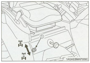
To engage/disengage 4wd:
- Stop tractor
- 4WD lever in up position
- 2WD lever in down position
Note: Neilo Broom Tractors are locked in 2WD To avoid excess tyre wear and scuffing on new seal.

Decal above is located by joy stick
Joystick control to lift lower and angle
Push directly forward to lower broom
Normal operating position
- Push through detent to float broomFloat should only be used on very undulating surfaces Brush wear may increase in float position
- Pull directly back to lift
- Push to left to angle leftt (see decal)
- Push to right to angle right (see decal)
Note: Broom cannot be lowered with key off
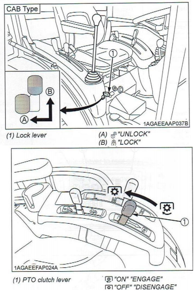 Safety locking mechanism
- A locking mechanism is located at the front of the joystick.Lock before dismounting machine!
To engage & stop broom drive
- To engage broom push
- the PTO lever (1) forward
- To stop broom pull lever backSee tab 4 re. monitoring pto RPM
Caution never ½ engage lever, slippage & excess wear may occur
If the operator leaves the seat with the PTO broom drive engaged the safety switch will stop the engine, to override and operate PTO broom drive while out of the cabin engage the parking brake then engage PTO
Keeping Dust Out Of The Cabin
- Keep all windows and doors shut
- Turn on blower with or without air conditioning
- Set to FRESH to keep positive air pressure in cab, this will minimalize dust
- The lever may have been locked or removed in correct FRESH position in some tractors
 Replacing Brush Sections
- Stop engine and lower close to ground
- Remove 16mm Lock nut LH end of broom
- Remove large nut on LH end of broom
- Remove LH end plate and worn brush section
- Fit new brush sections and replace spacers and reverse above procedure
- Spacers may need to be trimmed with grinder to suit the various brush options, spacer should not protrude past end of square shaft
If brushes are to be re-bristle 25mm of bristle must be retained
We recommend NZ Brush Company brushes
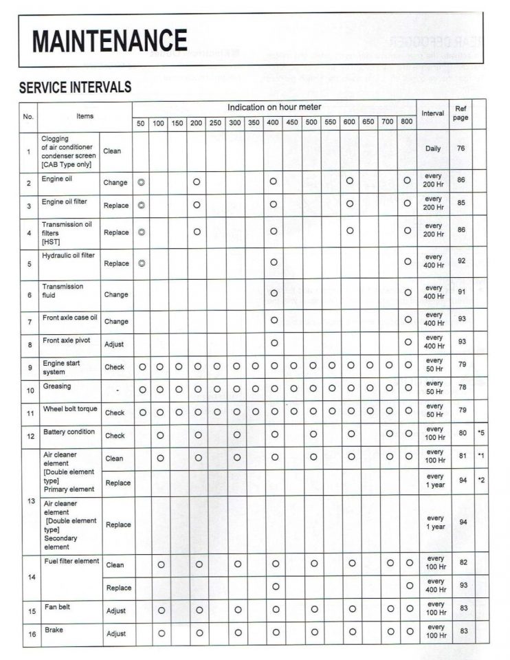
Daily & Weekly Service Checks

- Check engine oil level and cooling water daily
- Greasing-There are twelve grease nipples requiring one shot of grease daily
Important
It is possible to over-grease the spring loaded pivot causing it to lock. If this occurs, remove grease nipple, cycle pivot and release excess grease, replace grease nipple.A locked pivot will cause premature brush wear!

- Top spin Pre-cleaners automatically eject the dust and Do not require to be emptied
 Weekly: Squeeze vacuator on bottom of long pre cleaner pipe to release potentially trapped water
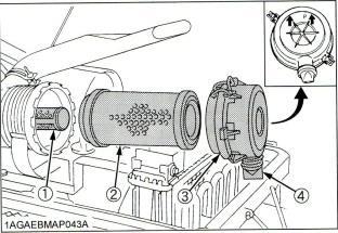 Check & Clean all screens daily
- Check primary air filter weekly
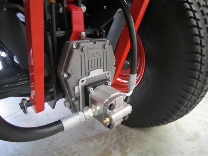 Check site glass on PTO step up box weekly, top up with Kubota UDT oil (same as transmission)
- Note: Change oil in step up box when trans. oil changed
 Breather only, not to be opened
- Top up or change oil via filter
- Check oil level of hydraulic reservoir, oil should be aligned with top indicator
- Check tyre pressures weekly, Front 25 PSI, Rear 16 PSI
Note rear tyres are 50% filled with water ballast
CHECK DAILY FOR OIL LEAKS AND REPORT IMMEDIATELY TO YOUR SUPERVISOR OR SERVICE PROVIDER
Part Numbers & Oils
- Engine oil Filter part # HH160-32093
- Fuel filter part # 6A320-59930
- Hydraulic filter part # HH670-37710
- HST filter part # HH660-36060
- Air Filter (outer) part # 6C060-99410
- Air Filter (Inner) part # 32721-58242
- Air Conditioning Filter part # T1855-71600
- Fan Belt part # 6C430-59280
- Compressor Belt part # T2055-79320
- Cab key part # 15248-63700
- Ignition key part # T0270-81840
- Broom Filter MF1002P10NB
- Broom Bearing UC207 self aligning bearing & F207 bearing block
Oils
- Engine oil: Kubota Engine oil API CH4 15W40 / BP C6 Global
- Transmission oil: 15L (TTF) Tractor Transmission Fluid
- Transmission oil: Kubota UDT-GL4 or Super UDT-GL4 / BP Traction TF10 classification API-GL4
- Front axle case: 4.7 L same as tractor transmission
- Broom Hydraulics: 58 L HD46
- Step up box: same as tractor transmission, fill to site glass only (do not overfill)
GREASE
- General purpose grease